|
Derek Fountain : ZX Spectrum DC-DC Converter
Programmer, Writer, Consultant, ZX Spectrum Hardware Hacker
|


|
|
|
|
|
|
|
|
|
|
|
|
|
|
|||

|
|||

|
|||

|
|||
Almost all of the following was written under the Creative Commons licence by Tomaz Solc in a blog post at tablix.org. Tablix went down in early 2024 and I managed to pick up the page from the Internet Archive. I wanted to preserve it. I made a few small tweaks to improve readability and added an oscilloscpe trace. I left the bits I didn't understand alone. :)
The Sinclair Spectrum has a small DC-to-DC converter on the motherboard. Together with a standard 7805 linear regulator it provides -5V and +12V voltages required for various CMOS chips in the computer and is a little marvel of analog electronics of its own. It manages to perform its function with just two transistors and a couple of diodes, compared to hundreds in modern converters.
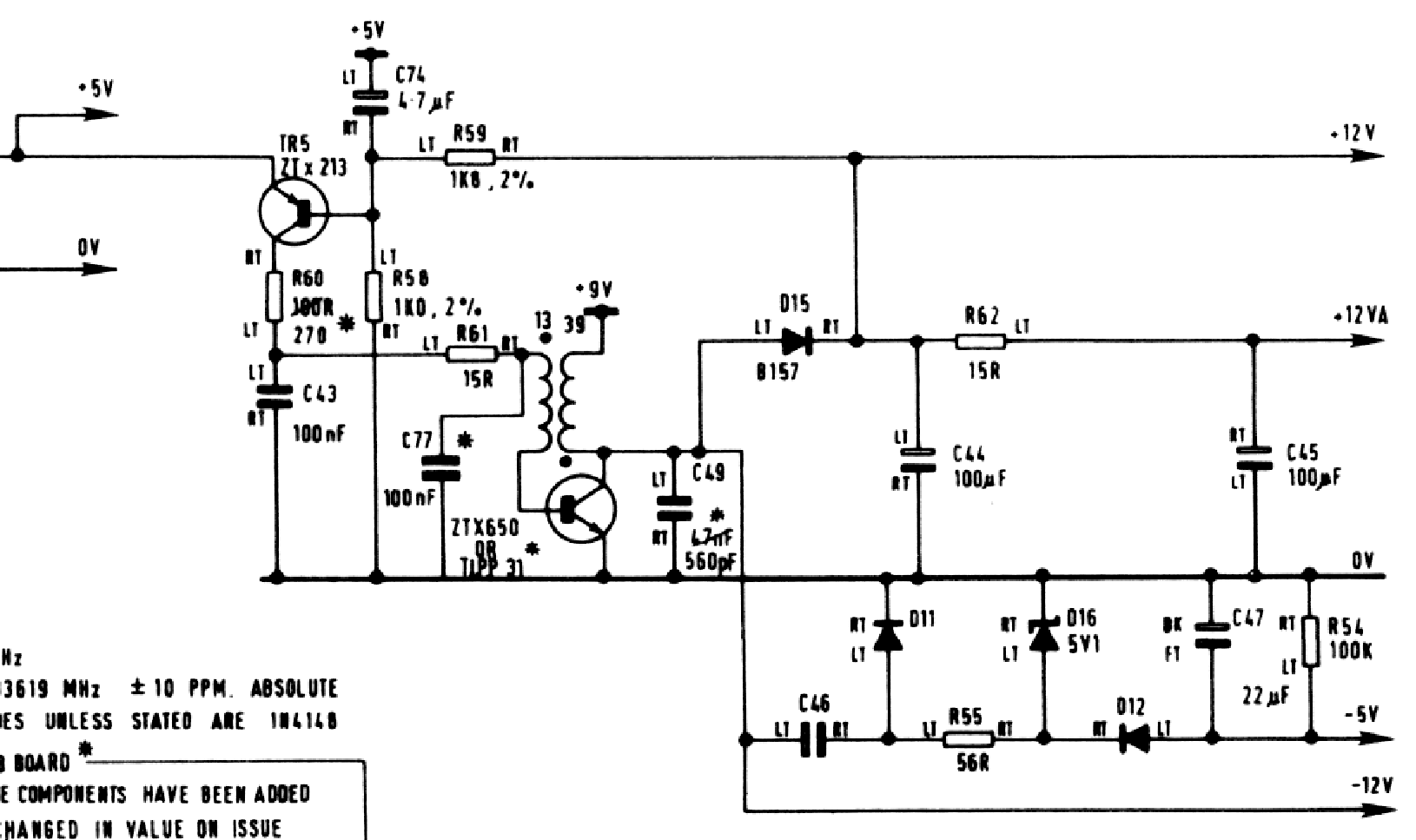
I haven't found any description of this type of converter on the web and I really think it deserves one, so I'm posting it here (it took me quite a while to figure it out). The circuit diagram below is from the Issue 3 Spectrum (not 3B). You might find it easier to pick up the full version hosted here.

DF here: I was interested in the 12V side (as opposed to the -5V side). The principle of operation, I think, is as follows: there's a small transformer with 3:1 ratio (commonly known as "the coil.") The nominal 9V from the PSU is connected to the side with the higher ratio winding. When the NPN transistor (TR4) starts to turn on the 9V connects to ground and 3V appears on the other winding. This boosts the current into the transistor's base and the transistor turns on hard. Current flows through the coil from the 9V supply building the magnetic field. When the transistor turns off (see below) the field collapses causing a voltage spike to around 15V which is smoothed into 12V. That 12V is fed via a voltage divider into the base of the other transistor (TR5) which regulates the 12V supply by throttling the voltage into TR4's base. The circuit oscillates, causing a stream of spikes which are turned into smoothed and regulated 12V.
And now back to Tomaz's write up:
Two voltages enter into the circuit: on the left edge is stabilized +5V from the 7805 and on one end of the right coil is an unstabilized voltage (around +9V) from the transformer in the power brick.
How it works? Let's say there is already a voltage on the +12V line on the top right. You can notice that the voltage divider R59 - R58 divides this voltage down to around +4.3V (also notice the big capacitor C74 - the divider also works as a low-pass filter and has a large time constant of around 5ms). From here, we can see that the PNP transistor TR5 works in the active region. Veb is around 0.7V while collector has a relatively small resistance R60 in series.
The constant collector current from the transistor charges C43 and C77 (you can ignore R61 for the moment). Let's say that the NPN transistor TR4 is off at the moment. There is no current in the coils and the voltage on C43 and C77 is equal to the base voltage of this transistor.
When the voltage on the capacitors reaches around 0.7V, TR4 starts to turn on. Suddenly, there is a constant 9V of voltage on the right coil. The current in the right coil begins to rise linearly and, because the coils are coupled, a voltage of around +3V appears on the left coil (notice the ratio of number of turns and the polarity). This increases the base voltage and further turns on TR4. However, TR5 now can not provide enough current that is flowing into the base and C43 and C77 begin to discharge. When they discharge to around -2.3V, TR4 turns off. Since current flowing in the right coil can not stop so quickly it flows through D15 and charges C44, which raises the 12V line a bit. With TR4 off, TR5 can again begin to charge C43 and C77 until TR4 starts to turn on again and the cycle repeats.
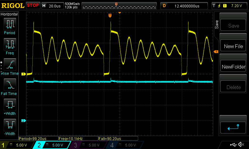
DF:Here's the waveform from the higher voltage side of the coil at 5V/div. It spikes to over 15V then settles back down, dropping back to 0V as TR4 turns off. Note that I run my research Spectrum from a bench PSU which provides it 7.8V, not 9.0V. I'm not sure that makes any difference to the levels seen here.

There is of course a negative feedback loop here: When the voltage on the +12V line increases, the voltage of the voltage divider turns off TR5 a bit. This means lower collector current and slower charging of C43 and C77 and longer time interval between cycles. Voltage stabilized by 7805 basically works as a reference for the +12V line.
-5V line on the other hand is a standard charge pump. It uses the approximately square voltage on the TR4's collector to discharge C46 through D11 when the voltage is high and charge it into C47 when the voltage is low. Zenner diode D16 serves here as a voltage reference.
Why there is a -12V line marked here is a bit of a mystery for me, because the voltage on that line is neither constant nor negative.
DF: The "-12" on many circuit diagrams is actually an artefact from the "~12" label on the original, indicating there's an unstable 12V at that point.
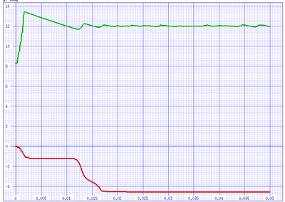
How it starts? At power-up, +12V line is at +9V (charged up through the coil and D15 with TR4 closed). TR5 is fully on and C43 and C77 quickly charge up. Transistor quickly turns on fully and a current begins to flow through the coil. Here possibly R61 comes into play (I'm not entirely sure) and prevents TR5 from keeping C77 charged long enough for TR4 to close and raise +12V enough to turn off TR5. On the simulation below, you can see a large overshoot on the +12V line at start-up

At the end a few notes about failure modes (while this circuit is ingenious, it also seems to be the most common thing that fails in spectrums, according to various web forums I've seen): If for any reason the oscillator does not start TR4 will remain on and will short-circuit right side of the coil. A couple of amperes will flow through, destroying TR4 and possibly also the coil. How can this happen? My tests show that if the +12V line is overloaded (due to a shorted RAM chip, for example, or a shorted electrolytic capacitor), the circuit will self destruct. Another important thing to note is that this circuit will not work (and will again self destruct) if the supply voltage (voltage from the power brick) is higher than 12V. This is not such a remote possibility - I have here an original Sinclair power brick that gives out 15V and will happily destroy any spectrum that will be connected to it.
DF: The original Sinclair power brick puts out about 14V unregulated. It relies on the load from the Spectrum itself to drag it down to about 9V which means the voltage it's providing for the coil is about right.
Unfortunately TR4 has to survive large base currents and large collector voltage spikes from the coil. It's not very easy to get such transistors on the market. I'm currently experimenting with a ST13001 transistor I got from old "energy saving lamps" and it seems to be working fine here (by the way: these lamps use a similar simple oscillator design, although they use rectified network voltage of around 300V instead).
DF: Suitable replacements are available: TR4 (which was a ZTX650) should be replaced with a ZTX651 or ZTX653. TR5 (which was a ZTX213) should be replaced with a ZTX751.
Another point is that the -5V supply will work better on lower supply voltages (lower supply voltage, higher switching frequency due to less current pushed through D15 at each cycle. Charge pump can pump more charge if the frequency is higher).
I'm not quite finished with experimenting with this circuit. At the moment, I'm testing how tolerant the circuit is to different coil inductances. I have no idea what inductance the original coil in the spectrum has, but I tried did a guess at 100?H/900?H and the converter seems to be happy with it.
DF: Tomaz wrote this in 2006, so I guess he's done with it by now. :)
Distributed under the Creative Commons licence. Copyright Tomaz Solc 2006 and Derek Fountain 2024.
Site and content Copyright 2023 Derek Fountain - All Rights Reserved
