|
Derek Fountain : ZX Spectrum Diagnostics Board
Programmer, Writer, Consultant, ZX Spectrum Peripheral Designer
|


|
|
|
|
|
|
|
|
|
|
|
|
|
|
|||

|
|||

|
|||

|
|||
Whenever someone pops up on one of the Sinclair related retro-computing forums with a non-working ZX Spectrum, the initial approach to investigation is always the same: start by measuring the voltages, +5V, +12V and -5V. Then the next question is "what test equipment do you have?" If they have an oscilloscope or logic probe they can measure a bunch of useful signals to get an idea if the Z80 and ULA are working.
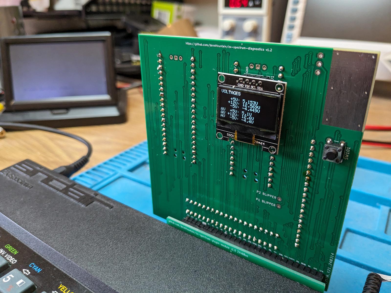
It occurred to me: wouldn't it be useful if a device could be plugged into the machine which could sample those voltages and signals and report back what they are? It wouldn't be a magic diagnostics bullet because there are lots of faults that can't be detected from the Spectrum's rear edge connector, but as a way to collect initial information it might be rather handy. So I made one.

Lots more photos at the github repository.
Here's a video demonstrating the device:
The board has two Raspberry Pi Picos on the back, and a small screen on the front. The firmware runs various tests and reports the results to the screen.
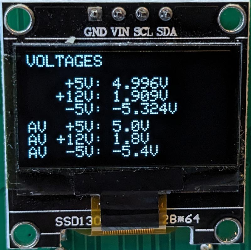
It works rather well. I currently have a dead ZX Spectrum bought from eBay which hasn't had a video modification made, so it's hard to tell just how sick it is. I plug this board in and can see that actually it passes all tests except the +12V voltage one:

The ULA and Z80 are OK (as far as the firmware tests can tell) and the Z80 is correctly running the ROM code. So it's not a particularly sick computer, which is good to know.
The RP2040's main limitation with retro-computing projects is the lack of GPIOs. With 8 bits of data bus and 16 bits of address bus, the Pico's 26 GPIOs are almost immediately used up. So for this project I added a second Pico. The second Pico is connected to the address lines while the first Pico does everything else. There's a synchronisation signal between the two Picos, and a PIO based data channel for them to share the address line information. Hopefully the next version of the RP2040 will have more GPIOs and this sort of over-design won't be necessary.
The voltages are sampled by the RP2040's ADCs, fed from the Spectrum's power lines via voltage dividers. The dividers use the Pico's 3V3 as a reference since that's guaranteed to be more stable than the Spectrum's +5V power line. The +12V line is sampled with clamping, so it's very unlikely to damage the Pico no matter what level it's at.
The RP2040's very clever PIO hardware is used to count the 3.5MHz clock signal from the ULA. It can easily count all the individual clock cycles the ULA puts out. When the Z80 is held in reset the Spectrum's memory contention doesn't happen; when the Z80 is allowed to run, it does. Thus the board can count clock cycles in both contended and non-contended scenarios.
Most of the signal line checking tests just check that the line is seen transitioning from low to high, and high to low. They're checking that the lines aren't stuck. It would be possible to do a lot more, including running a full sample of all the signals in order to do a complete analysis of what the Z80 is up to. A project for another day, maybe.
The ROM test utilises both Picos because the address, data and control buses are split up across the two Picos. A synchronisation signal on a GPIO is used to start the test simultaneously on both devices. The control bus is monitored to detect memory reads (i.e. when both /MREQ and /RD are both active) and the addresses being read are stored in an array. The sequence of addresses the Z80 progresses through as it runs the code at the start of the Spectrum's ROM is totally deterministic, so the sequence seen can be compared to the sequence expected.
Lots of screenshots, operation details and discussion of how it works are in the github repository, along with circuit design and full source code.
This was an interesting project to work on, full of little subtleties about electronics which I've not come across before. If anyone wants to make one and needs help, just ask. I'm happy to help anyone who's interested in the project.
Derek Fountain, March 2024
Site and content Copyright 2023 Derek Fountain - All Rights Reserved
