|
Derek Fountain : ZX Spectrum ROM Interface
Programmer, Writer, Consultant, ZX Spectrum Hardware Hacker
|


|
|
|
|
|
|
|
|
|
|
|
|
|
|
|||

|
|||

|
|||

|
|||

A ZX Spectrum external ROM interface is a fairly straightforward device to create. The Spectrum is designed to support them, and we've had them since the 80s. Relatively simple they may be, but no fledgling ZX-hardware-hacker can claim their stripes before they've made one. So I figured I'd better make one. :)
The normal way to make one of these is to use a standard ROM or EEPROM chip, but where's the fun in retreading so much ground? I did mine a different way. I used a Raspberry Pi Pico microcontroller which I programmed to emulate a ROM device.
The basic design involves setting 16 of the Pico's General Purpose Input/Output lines (GPIOs) as inputs, then connecting them to the 16 lines of the Z80's address bus, along with the Z80's /MREQ ("memory request") line. When /MREQ goes active and the address on the address bus is in the range $0000 to $3FFF, that means the Z80 is accessing a byte in the ROM. When this happens the Pico needs to go to the 16K memory image it's using as the ROM, find the byte at the offset the Z80 is requesting, and apply the 8 bits of that byte to 8 output GPIOs connected to the Z80's data bus. Thus when the Z80 does a ROM memory request the byte appears on its data bus and the Z80 has no idea it just spoke to a microcontroller instead of a 1980s ROM chip.
The Raspberry Pi Pico does have a bit of a drawback for this sort of project though: it's only got 26 GPIO pins. With 16 needed for the address bus and 8 more needed for the data lines, plus /MREQ, that's pretty much them all used before anything else is considered. No one said this was going to be easy. :)
The real issue is speed. The RP2040 processor on the Pico is clocked at 133MHz. Page 8 of the Z80 manual says that the timing for the Z80's "M1", the instruction-fetch cycle, is the most time critical. In this case the Z80 puts the address it wants to read on the address bus then activates /MREQ. The Z80 then reads the data byte off the data bus exactly one and a half clock cycles after /MREQ goes active. There's no "it's ready" flag or anything like that. The Z80 just assumes the memory makes the data byte available quickly enough. On the Spectrum's 3.5MHz Z80, one and a half clocks is (taps on calculator) 4.28571428571e-07 seconds, which is about 430 nanoseconds, a nanosecond being one billionth of a second. Most machine code instructions on the RP2040 processor execute in one clock cycle (unlike the Z80 which takes anywhere between between 4 and 23 cycles per instruction). One clock cycle at 133MHz is about 7.5ns, so in 430ns the Pico can run (tap-tappity-tap) 57 machine code instructions. Hmmm. 57 machine code instructions to read the GPIOs, sort out the address lines into a 16 bit number, find the value at that offset in a 16K buffer containing a ROM image, then sort out the 8 bits of that value and put them on 8 GPIOs ready for the Z80 to pick up? Might be a bit tight, this.
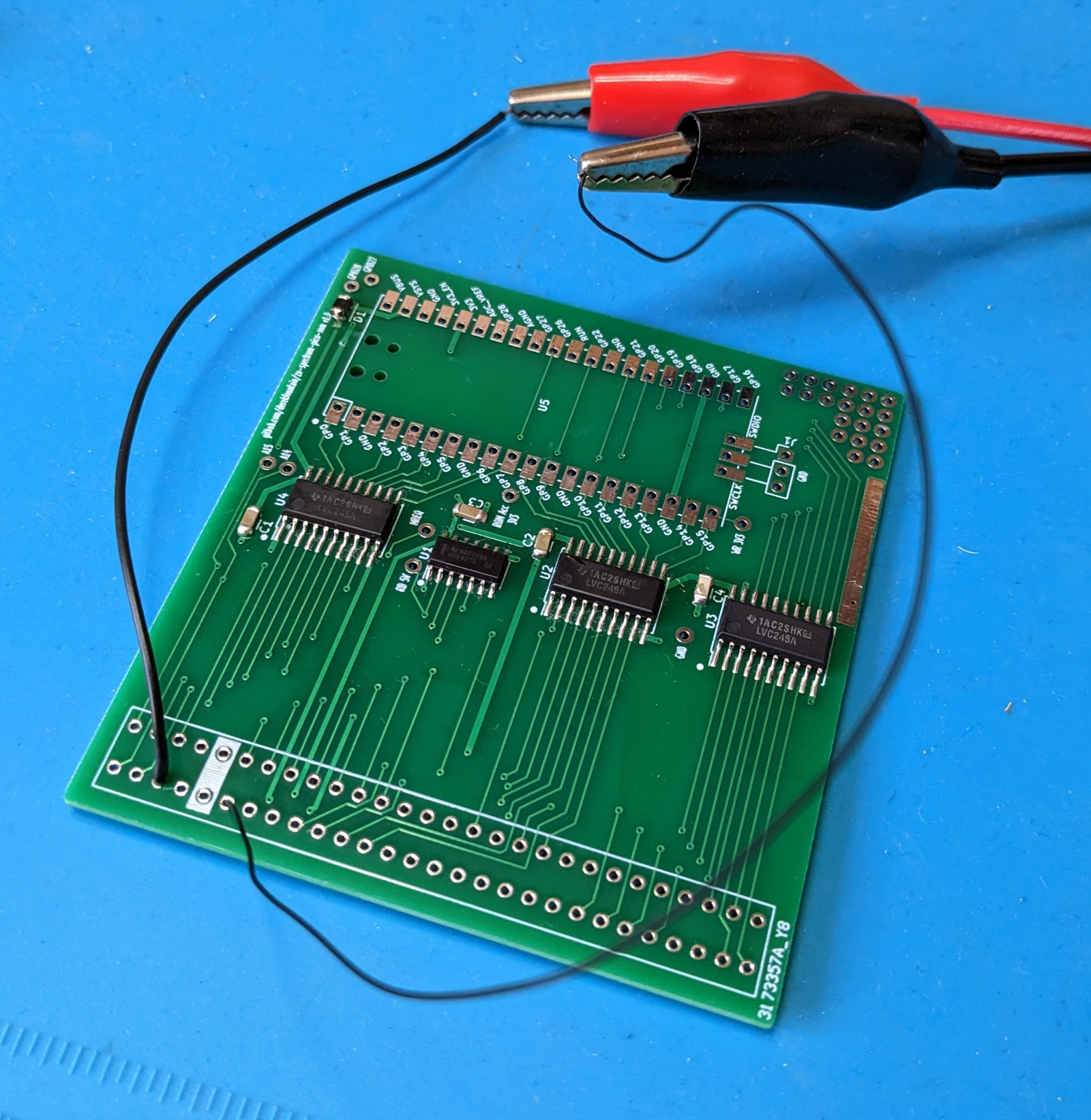
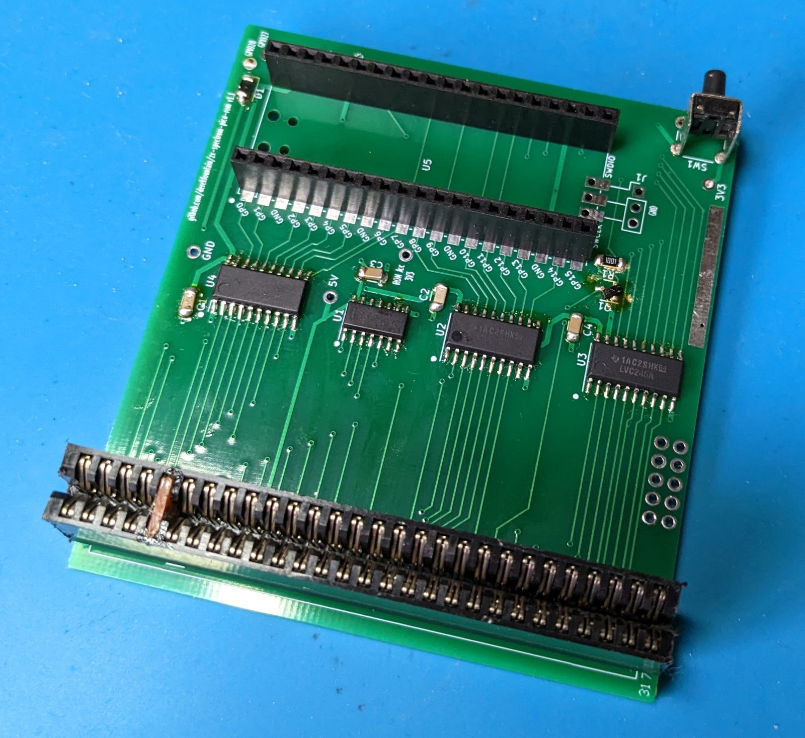
"Oh well," I thought. "Only one way to find out, and it's not going to build itself." So I made a design, sent it off for fabrication, and when the boards arrived I built one. I don't tend to plug v1.0 experimental boards straight into a Spectrum, so, with not even a Pico attached, I powered it directly:
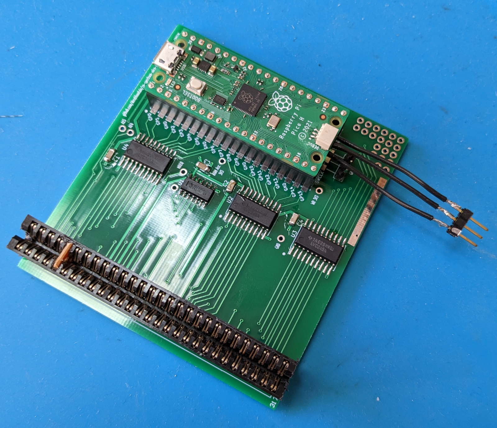
Nothing went bang and the bench PSU said nominal current draw, so I added the edge connector and the Pico:
I wrote the initial software for the Pico, programmed it, and plugged the device in. Did it work? It did not.
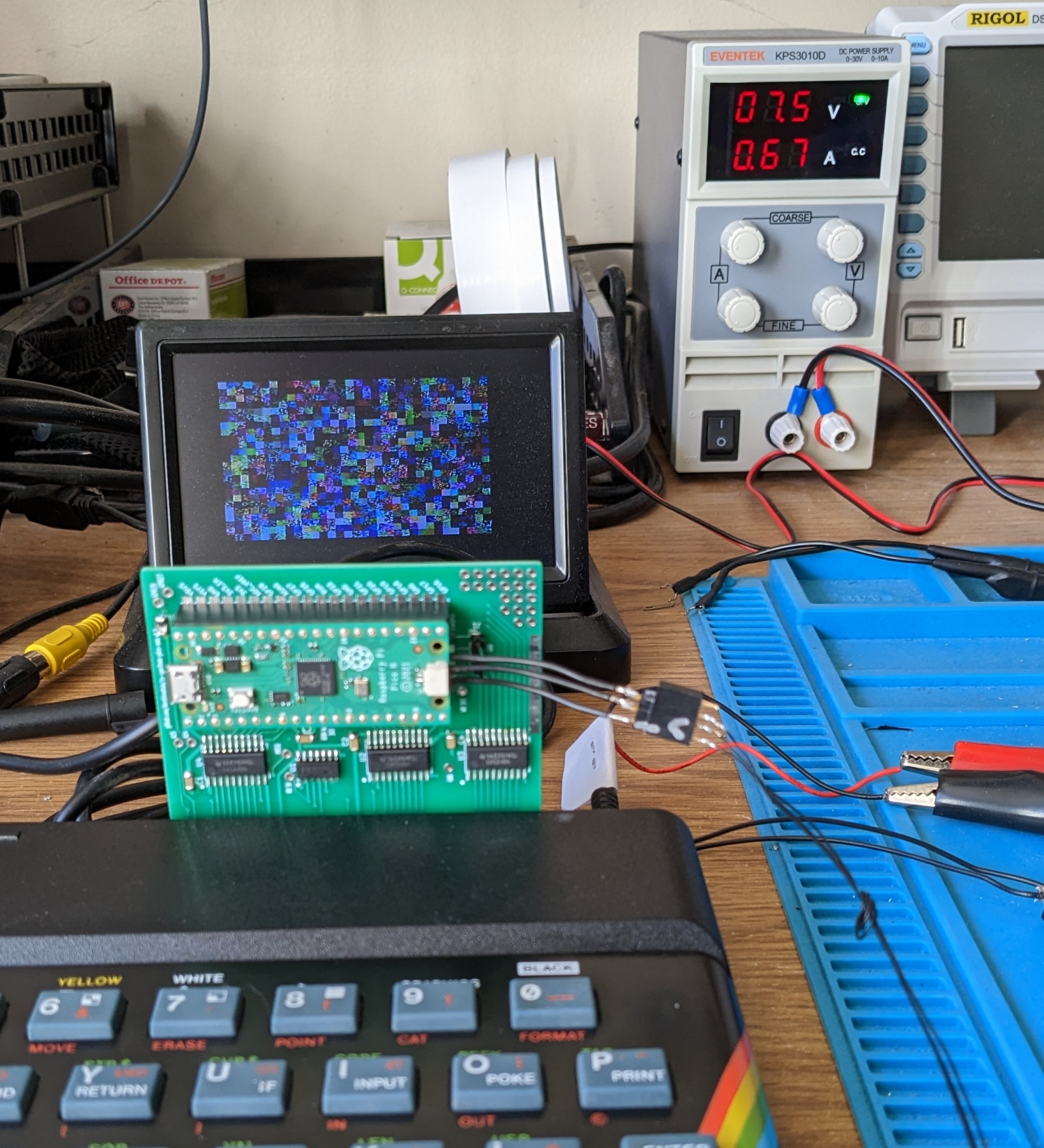
It turned out that the initial problems were all Pico software related, and after some debugging and updating, I got it working. The hardware prototype was actually correct first time. Note how I changed the copyright date in the ROM image so I could tell my ROM was working and I wasn't just seeing the Spectrum's ROM:
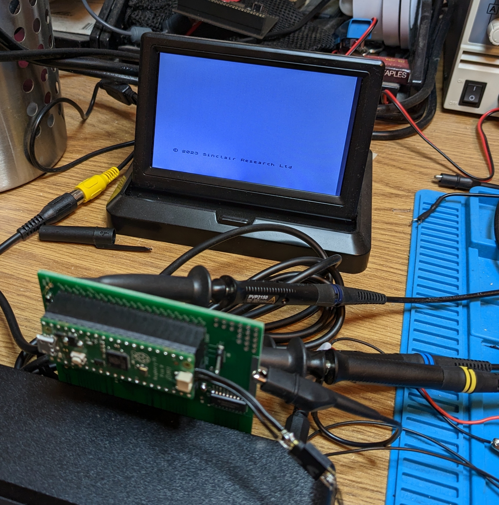
The board is designed to take complete and permanent control of the ROM image. (For the initiated, it permanently asserts the /ROMCS line, disabling the Spectrum's ROM chip.) The default 16K ROM image in the Pico's memory is the original 1982 ROM, so with the emulation software working the Pico supplies the exact bytes the original ROM chip does. But it can actually supply whatever it likes.
The idea at this point was to have several ROM images on board and have the active one selectable. So the plan was to load up some ROMs - original, bugfixed, diagnostics, GOSH, the games ones - and have a selection method the user could use to select the one they want. The Pico code for fetching a byte from the active ROM image and handing it back to the Z80 is this:
      uint8_t rom_value = *(rom_image_ptr+rom_address);
      gpio_put_masked( DBUS_MASK, rom_value );
The rom_address is the address the Z80 has asked for. rom_image_ptr is a pointer to the 16K buffer holding the currently active ROM image. Therefore changing the ROM which the Spectrum sees is as simple as changing the data buffer rom_image_ptr points to. I could do this on a button press, or programmatically.
The important thing the prototype was missing was the ability of the Pico to reset the Z80. The Pico would switch the ROM and the Z80 would continue running as its program was abruptly changed underneath it. This didn't end well. So I needed to add the ability for the Pico to change the ROM image, then reset the Z80. I'd had some vague idea about using the /WR line to detect writes to ROM. In practise this seemed superflous, so I cut those tracks and wired up the Z80's /RESET line via a transistor so the Pico could pull the /RESET low. I added a couple of switches, which led to this:
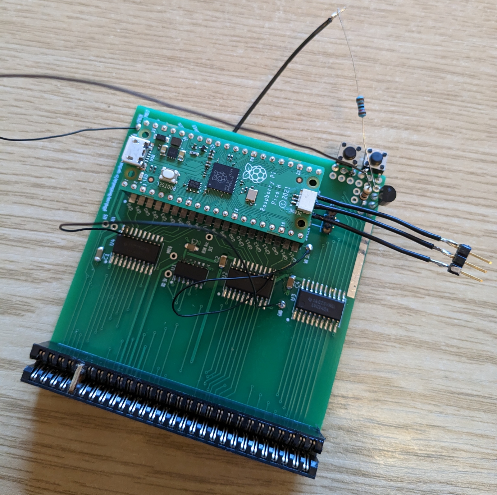
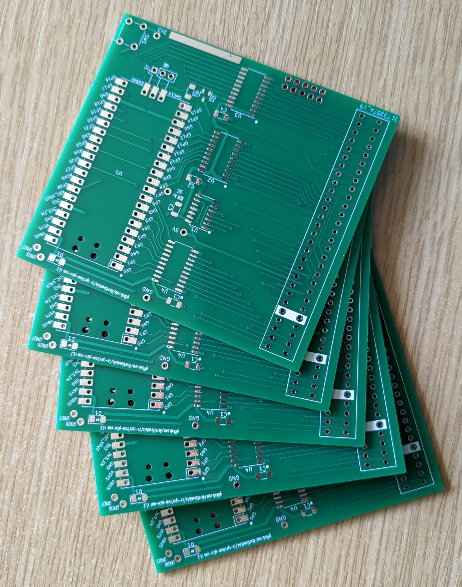
This worked reasonably well. The switches were a bit wobbly, and it turned out I only needed one, but the Pico being able to control the Z80's reset solved a lot of problems. So I sent the v1.1 design off for fabrication. They arrived back:
and I built one:
This board needed a couple of fixes (notice the rotated transistor to the bottom right of the Pico sockets, oops). But it works. The software in the Pico cycles the list of compiled-in ROMs when the button is pressed. Here's a wobbly demonstration YT video:
The project is open and free under the GPL, its design and source files are all available on my Github page. There's a bit of discussion about it at Spectrum Computing.
Site and content Copyright 2023 Derek Fountain - All Rights Reserved